Back to Design Solutions
Our Solution to the Self-Starting Problem
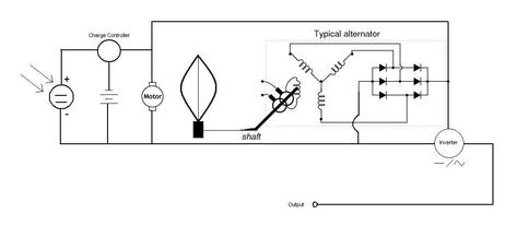
Our intended solution to the self-starting problem of the Darrieus vertical axis wind turbine that differs from other solutions is the incorporation of a solar panel. As seen in Figure 2, our proposed schematic, the solar panel will be capable of charging and maintaining a battery that will power a dc motor. The dc motor will be used to keep the turbine spinning even in times of low wind. Our intended design is to have the motor disengage from the turbine when the wind gets the turbine spinning fast enough (less than 3mph winds are all that is needed to allow the turbine to rotate under its own power). To accomplish this, a microcontroller will be installed into the system that will disengage the dc motor once the turbine is under its own power. The turbine itself will run directly into an alternator which eliminates the need for gear boxes. The alternator is built to output a dc voltage so in order to use the energy that will be stored in the batteries the entire system output will be run through an inverter to change the dc voltage to an ac current which is what household appliances operate off of.
The solar panel chosen is an amorphous panel. This type of solar panel is more appealing than a standard monocrystalline silicon panel because it is made to work regardless of direct sunlight. Even in times of low sunlight or cloudy days this panel would still be capable of emitting a voltage to maintain the battery.
The solar panel chosen is an amorphous panel. This type of solar panel is more appealing than a standard monocrystalline silicon panel because it is made to work regardless of direct sunlight. Even in times of low sunlight or cloudy days this panel would still be capable of emitting a voltage to maintain the battery.
Blade Design
|
Design 1
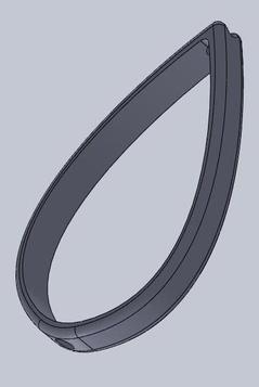
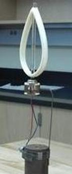
The first design solution consisted of a simple Darrieus two blade design. This design was drawn up in SolidWorks and printed out in the Makerbot 3-dimensional printer. There was no specific size designated for the blades. We tried to maximize the printing area offered by our 3-D printer which is 105mm x 120mm and about 130mm tall. The tear shaped two blade designs was created with holed on the top and bottom which was approximately 6 mm. After the blade was printed, we inserted a plastic shaft through the holes and secured it tight on both locations. This pole was attached to a dc motor and held appropriately by a weight for testing in the wind tunnel. The images below show the CAD part in SolidWorks and the assembled Design #1. |
|
|
|
Design 2
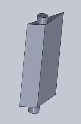
The second design also utilized the 3-D capabilities offered on our campus. However it is drastically different from our first design. Instead of curved blades we chose to create straighter and simpler blades. We also decided to increase the number of blades to ensure that it would spin. The blades were designed with two cylindrical notches of diameter equal to 0.25 inches on the top and bottom of the blade. Again we tried to maximize the printing area offered by our 3-D printer which is 105mm x 120mm and about 130mm tall. This design was created to help the assembly of the project. The design plan was to use two plexiglass plates in order to attach blades to from the top and bottom. The plexiglass would be prepared with three equidistant holes of diameter 0.25 inches for the blades to be inserted. The plexiglass was perfectly round with a diameter of 4.7 inches. A shaft would again run through the center of the two plexiglass that held the blades then it would be attached to a dc motor. |
|
|
|
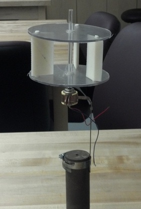
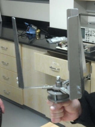
Design 3
The third design was different from the previous two design failures. It did not utilize the 3-D printer for the design of the blades. It was also not mounted on a dc motor, but rather on an alternator that was premade for attachment of a three bladed turbine design. The blades were made out of aluminum and the dimensions are stated below. The three blades were attached to an L bracket through two bolts and nuts. The size of the L-brackets was elongated to maximize the width of the swept area of the three blades turbine to 9 inches while still being able to fit it in the wind tunnel. The wind tunnel was 12 inches wide. 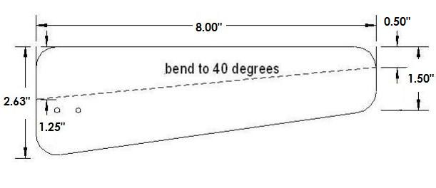
|
|
Click here to see a video of Design 3 spinning in the wind tunnel.
